1. Overview of its equipment and systems The boilers No. 1 and No. 2 were designed by Foster-Wheeler (USA) and manufactured by Foster Wheeler of Spain. They are subcritical, single-drum, single hearth, An intermediate reheat and natural circulation boiler, the reheater system uses the flue gas damper to adjust the temperature, and the burner uses the front wall arrangement swirl burner. Low-rank and high-rank economizers are arranged in a cascade arrangement, low-rank economizers are arranged in the mixed flue at the back of the flue gas dampers, high-rank economizers are arranged in the lower part of the low-temperature superheater of the front flue, and the economizer feeds steam drums The water is introduced from the east end of the steam drum through a water supply pipe. After entering the steam drum, it is divided into two. The two water distribution pipes have water distribution holes along the length of the steam drum. Units 1 and 2 were put into commercial operation in the first half and the second half of 1993 respectively.
The design parameters of the boiler at ECR are: load (ECR), 350 MW; main steam flow, 1075 t/h; superheated steam outlet temperature/pressure, 541°C/17.2 MPa; feedwater temperature/pressure, 280°C/l 9.24 MPa; Hot steam inlet temperature/pressure, 309°C/3.14MPa; reheat steam outlet temperature/pressure, 541°C/2.98MPa; economizer outlet temperature, 313°C.
Second, the pre-transformation operation After the unit was put into operation, it was found that there was a deviation in the water level on both sides of the steam drum. This deviation increased significantly with the load increase, but did not change with the actual water level of the steam drum. The steam drums are equipped with 2 and 1 heavy-duty water level transmitters on the east and west sides, respectively, and a two-color on-site water level meter is installed on each of the east and west sides. The west side is also equipped with an electric contact. Water level meter. Both the water level transmitter and the in-situ water level 8 are consistent in that the deviation of the water level on both sides of the drum is consistent. In order to check and confirm the water level of the drum, the water level of the drum was measured by an external plastic U-tube. It was found that the water level on the west side of the steam drum is 17Omm higher than the actual temperature on the east side under the rated load. Therefore, it is possible to eliminate the cause of the water level measurement and confirm that the water level measurement is accurate. In addition, during the overhaul of the furnace shutdown, the internal inspection of the steam drum can clearly show that there is a markedly low east-west high water mark, indicating that the deviation of the water level on both sides of the drum is long-term. The original design was equipped with two water level switches on the west side of the steam drum and one water level switch on the east side. The water level protection of the drum was achieved by the water level switch. Due to the water level deviation, the unit tripping fault caused by the water level protection action often occurred in the first few years of production. For this reason, the order of the starting positions of several steam drum safety doors was adjusted, and the water level switch was also subjected to strong pull to try to avoid the steam drum. Water level protection frequently operates, but the effect is limited. Before and after 2003, according to the new specification requirements, the drum transmitter was replaced with a water level switch. Although the failure of water level protection malfunction will not occur again, it still does not fundamentally solve the problem of large deviation on both sides of the water level of the steam drum. .
The factors affecting the fluctuation of the water level of the drum generally include the imbalance of the input and output of the working medium, the pressure of the drum, and the change of the steam vapor volume of the steam drum. Among them, the steam drum pressure and the steam vapor volume of the steam drum mainly depend on the variation of the boiler combustion deviation. The results of long-term operation and special tests have shown that although there is deviation in the combustion in the hearth, the deviation between the middle and the two sides is mainly large, and there is no obvious difference in combustion and heat transfer between the two sides. Therefore, it can be considered that the fundamental cause of the large deviation on both sides of the east-west water level is the imbalance of the T-substance input on both sides.
Before the transformation, the inlet pipe enters the steam drum from the east end (A side) and enters the water in two ways. Each water distribution pipe has a water distribution hole in the county, as shown in Figure 1.

III. Analysis of Causes of Water Level Deviation on Both Sides of Steam Drum 3.1 There is a deficiency in the design of water outlet hole distribution of the original water distribution pipe. Although the original design has considered the influence of the static pressure distribution of the water distribution pipe, it is not considered sufficiently; according to the calculation results, the original design structure Under the full load (according to the 1200 avenge meter), the water output from the west is still nearly three times higher than that from the east, which is the root cause of the large deviation on both sides of the water level in the drum.
The calculation of flow deviation in the outlet hole is as follows.
(1) Calculate the static pressure increment at the outlet hole distributed along the distribution pipe of the water supply along the increment of the static pressure of the distribution pipe of water supply. (1)

In the formula: X is the relative length of the point to the origin of the coordinates; Hfp is the dynamic pressure head of the inlet of the drum water distribution pipe; αfp is the friction resistance coefficient per meter of the drum water distribution pipe.
(2) Calculating the flow distribution of the water distribution pipe Assume that the pressure in the drum is constant, the ambient pressure in the drum is P0, the static pressure at the inlet of the distribution pipe is P1, and the static pressure at each outlet hole is (P1+αχ); according to the outlet hole The pressure difference at the location, calculated from the Bernoulli equation, and the velocity of the outlet hole according to equation (2):
Where: Ï…fp is the specific volume of the medium in the drum water distribution pipe.
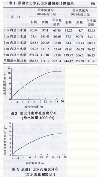
This method judges and considers the relative change of the water level of the drum through the water output per unit time of the outlet hole. This time we selected the high load (by 1200t/h water supply meter) and low load (600t/h), two kinds of typical operating conditions to calculate the distribution of the water distribution pipe outlet water outlet and outlet water velocity.
The calculation results are shown in Table 1, Figure 2 and Figure 3.
3.2 Deviation of the water level on both sides is not constant There is a certain rule for deviation of the water level from the east to the west of the water level: When the unit runs at a lower load below 22 OMW, the water level on both sides of the steam drum is basically not biased, and when the load starts to increase from 25 OMW, the deviation on both sides begins to be obvious. When it becomes larger, the west side (B side) is higher than the east side (A side), and the deviation when the rated load reaches about 15Omm. However, the east-west deviation of the drum level does not change with the actual level of the drum. Unit load changes cause changes in boiler evaporation and feedwater flow. Changes in feedwater flow have a greater influence on the static pressure phase flow distribution in the drum water distribution pipe, and also have a great impact on the deviation of the water level on both sides of the drum, so the transformation must consider load changes Impact on the deviation on both sides of the water level.
Fourth, the transformation program 4.1 transformation program content and characteristics The main content of the transformation program is: After the steamer into the jellyfish tube, is divided into two water distribution pipes on the north and south sides, the north through a throttle plate into the water distribution pipe In the effluent, in order to ensure the same head at the two distribution inlets, the resistance of the orifice plate is equal to the resistance along the south connecting pipe; the south side feeds water through the connecting pipe along the entire steam drum to the west, and then goes to the north to supply water Pipe out of water. The distribution pipes open two discharge holes, totaling 184, and the total number of holes is 368. The opening angles are respectively 30 degrees and 60 degrees with the horizontal angle, as shown in Figure 4.

Afterwards, the water level of drums 1 and 2 was checked under different loads. The test result proves that the reformation has reached the design value and fundamentally solves the problem of potential safety hazard caused by large deviation of the boiler water level on both sides of the boiler.
Take No. 2 furnace as an example. The results of the deviation of the water level on both sides of the drum after the reform are shown in Table 4.
The distribution of the water distribution holes is determined based on the static pressure characteristics on the water distribution pipes. The distribution characteristics of the water distribution hole determine the characteristics of the reform program: the static pressure at the water outlet hole of the water distribution pipe is distributed symmetrically along the east-west side of the steam drum, and the water outlet hole has no symmetrical distribution of the steam drum length, so the water level of the steam drum can basically guarantee the east-west side. Consistently, the deviation of the water level on both sides of the drum is affected by the change in load. At the same time, the specifications of the water inlet connection pipe are in accordance with the specifications of the original distribution pipe, which does not affect the access of the steam drum, but also ensures that the flow rate in the pipe remains unchanged.
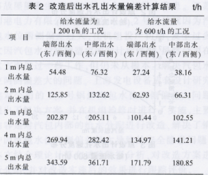
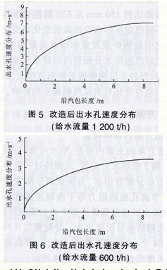
4.2 Calculation of flow deviation and flow rate after reconstruction Using the same calculation method, the calculated results of the flow deviation of the water distribution pipe after the reform under the different feedwater flow rates are shown in Table 2, and the distribution of the outlet water velocity of the outlet hole along the steam drum is shown in Figure 5 and Figure 6.
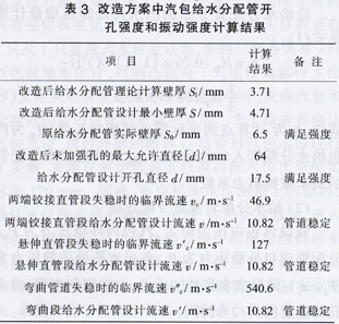
4.3 Water supply hole opening and vibration strength check of the water distribution pipe after reconstruction The reform of the water level on both sides of the steam drum involves the re-opening of the outlet hole of the water distribution pipe, and the water distribution pipe is a pressure-receiving element. Calculations determine whether the wall thickness of the newly designed feedwater distribution pipe satisfies the strength requirements, and whether new openings need to be truthfully reinforced to maintain the flow rate of the feedwater distribution pipe without changing the specifications of the water distribution pipe. Therefore, the feed pipe for the jellyfish pipe is used. Afterwards, water is fed into the water from the north and south sides; the water from the north side flows along the entire steam drum to the west through the connecting pipe, and then goes to the water distribution pipe on the north side. In this way, the east-west symmetry of the static pressure distribution of the outlet hole can be ensured without changing the flow velocity in the water distribution pipeline.
After verification calculation, the outlet hole of the water distribution pipe meets the strength requirements; the water flow rate in the distribution pipe (10.82m/s in case of high load) is less than the critical speed for vibration, and will not cause instability due to pipeline vibration.
The calculation results of the opening hole strength and vibration strength of the water supply pipe outlet hole in the steam drum are shown in Table 3.
5. The implementation of the plan and the evaluation of the effect have been calculated. By changing the water distribution system of the drum, the static pressure at the water outlet hole of the water distribution pipe is the same along the east-west side of the drum length, so as to reduce the deviation of the east-west side of the water level of the steam drum to meet the safety production of the unit. Needs. The volume of retrofit projects is very small, and the project budget is not large, which can solve the potential security risks of large deviations in the water level at the east-west side of steam drums.
During the mid-renovation period in September 2005, No. 1 furnace was reformed according to this plan for the water inflow distribution pipe of the steam drum; during the minor repair in April 2006, No. 2 boiler was used to implement the same reform of the water distribution pipe of the steam drum. .
In order to evaluate the actual operation effect after the reform, the water level of boiler steam drums No. 1 and No. 2 was checked under different loads after the transformation. The test results prove that the reformation has reached the design value, which fundamentally solves the problem of safety hazards caused by boiler deviations on both sides of the water level of the steam drum.
Take No. 2 furnace as an example, the deviation of the water level on both sides of the drum after its release is shown in Table 4.
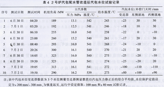
It can be seen from Table 4 that the reform of boilers 1 and 2 aiming at the deviation of the drum water level on both sides of the boiler drum level basically eliminates deviations on both sides of the drum level, and the deviation on both sides of the drum level after the renovation is not large. The random group changes and changes to achieve the desired transformation effect.
Breif Introduction of Biomass Pellet Mill:
ROTEXMASTER New designed vertical double Ring Die Pellet Machine from us is designed ,developed and manufactured by our factory, it have the special appearance, more reasonable structure and stability, mainly for sawdust, rice husk, peanut shell, bamboo shavings, palm fiber and other materials.
Features of Biomass Pellet Mill:
1.High automation, No need to take care.
In the process of operation, the control panel, tablet computer and mobile APP can be used to monitor the temperature of critical parts and the electric current of the equipment.
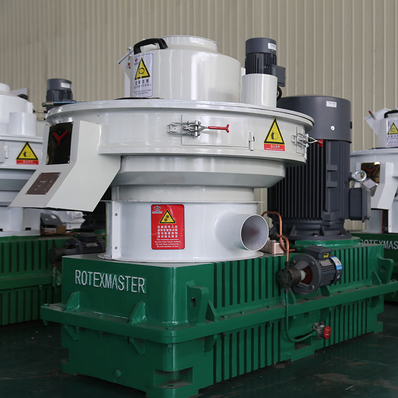
2.Independent lubrication and non-independent lubrication can be switched.
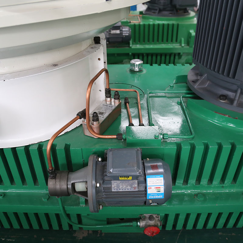
3.Reducer drive strengthen.
The gearbox adopts independent research and development big gear with 3 level drive , module increased , gear strengths increased , The gears in gearbox quality assurance for five years.
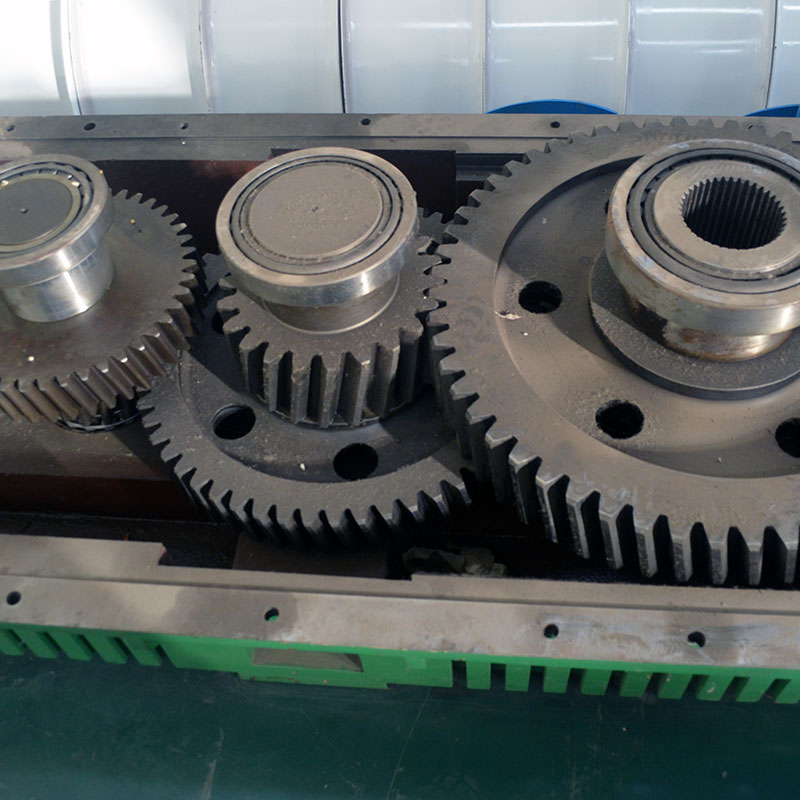
4.Die: stainless steel,with high wear resistance and high capacity.
Die of Biomass Pellet Machine adopt integral carburizing stainless steel, high wear resistance, good stability, discharge area increase, enhance the capacity and reduce cost.
Technical Parameter of Biomass Pellet Mill:
|
Model |
Power(kw) |
Diameter(mm) |
Capacity(t/h) |
Measurement(mm) |
Weight(T) |
|
YGKJ560 |
90+1.5+0.37+1.5 |
4-12 |
1-1.5 |
2600*1300*2300 |
5.8 |
|
YGKJ680 |
160+1.5+0.37+1.5 |
4-12 |
1.5-2.5 |
3300*1500*2300 |
8.5 |
|
YGKJ850 |
220+3+0.37+2.2 |
4-12 |
2.5-3.5 |
3800*1830*3080 |
15 |
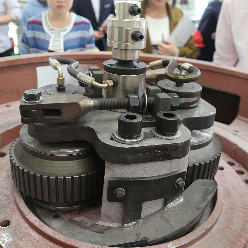
Details of Biomass Pellet Mill Machine:
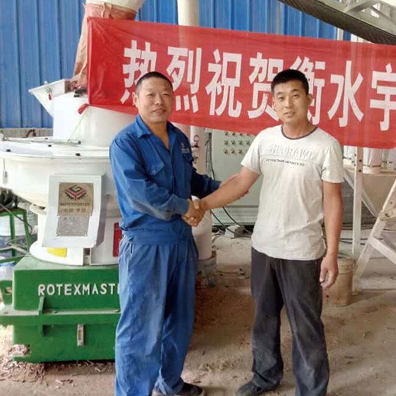
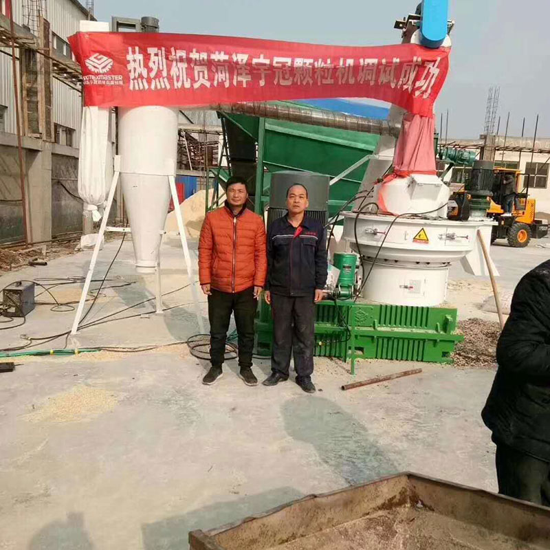
Customer Cases of Biomass Pellet Mill:
Biomass Pellet Mill
Biomass Pellet Mill,Rice Husk Pellet Mill,Rice Husk Biomass Pellet Mill,Wood Biomass Pellet Mill
Shandong Rotex Machinery Co.,Ltd , http://www.woodpelletmachinery.com
