As the “Anti-Countermeasure Implementation Regulations†and the previous design ideas are quite different, under the premise of ensuring the safe operation of the units, we must adopt the attitude of advancing with the times and seeking truth from facts to seriously solve the relevant technical problems arising therefrom. Main equipment protection, including transformers and transformers and transformers protection, due to the complexity of its own equipment, many varieties of protection, such as a complete 300 MW unit with 30 or 40 kinds of main backup protection, voltage transformer (TV), current transformer ( TA) There are one or twenty groups, and the protection of export signals reaches sixty to seventy types. There are also new engineering and renovation projects in the project. Many problems such as design and configuration, and some of them have not understood the complexity of the protection of the main equipment when implementing the "Anti-measurement Rules", they have created a "misunderstanding". Only by careful analysis of the "Anti-Execution Measures" and a comprehensive understanding of the protection configuration of the main equipment can we eliminate "misunderstandings" and truly improve the safety and reliability of the main equipment protection.
1 Configuration Experience Review A complete set of 300 MW unit protection including generator protection, boosting main transformer protection, high-voltage factory transformer (hereinafter referred to as high-grade transformer) protection and excitation excitation transformer protection. The protection of these major equipment can be divided into short-circuit fault protection and abnormal operation protection. The protection against short-circuit faults shall have primary protection and backup protection. The primary protection is to meet system stability and equipment safety requirements. The protected equipment shall be selectively removed at the fastest speed; the backup protection is used when the main protection or circuit breaker is refused to operate. Remove fault protection. Table 1 and Table 2 provide a brief description and classification of the generator and main transformer protection.
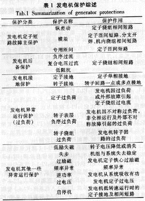
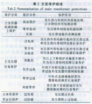
According to the relevant technical regulations and countermeasures, the major power design institutes have accumulated decades of experience, and the main equipment protection has had several “four-unification†typical designs. In 1999, the General Design Institute of Electric Power Planning and Design, together with the six major design institutes, compiled a typical digital protection design scheme for 300 MW units, which has the following salient features.
1.1 The main unit protection of the large unit is doubled and the circuit is independent When there is no circuit breaker between the generator and the main transformer, install the generator differential protection, transformer differential protection and large differential protection of the transformer. If there is a circuit breaker between them, the generator differential protection and the main transformer differential protection are installed separately. The main protection of the generator and the main transformer is thus doubled.
In the configuration, the generator differential, main transformer differential, and high plant differential and dynamic transformer differential protection are placed in different cabinets, and their TA secondary loop design is also independent, that is, from the input loop to The dual main protection circuit of the same component in the outlet circuit is completely independent and the reliability of protection is guaranteed.
1.2 Back-up protection The relevant rules of the unit itself clearly indicate that the power plants in which the large units are located generally have voltage ratings of 220 kV and above. These buses and lines are required to be equipped with two sets of rapid main protection, and their near backup protection is also relatively complete, and no longer needs change. Group protection provides it with far backup. Therefore, the reserve protection of the transformer protection group is only used as backup protection for the main protection of the transformer-transformation group, and it is indispensable.
1.3 Strengthening primary protection and simplifying backup protection As the main protection is promoted on a large unit, the backup protection operation is greatly reduced. The analysis of the operation of the protection device in recent years shows that the correct operation rate of various backup protections for generators and transformers is relatively low, such as low impedance protection, and the correct operation rate is only 30%. Some experts specifically put forward suggestions for strengthening primary protection and simplifying backup protection. Practice has also shown that this is a concise and practical principle that takes into account the requirements for the protection of reliability and safety.

In engineering design, TA for differential protection and TA for backup protection are independent, and their other protection circuits are completely independent. Transistor type and integrated circuit type protection hardware are used to build, and the main backup protection circuit is totally independent. The main backup protection in the “four unified†digital protection typical design is placed in different cabinets, and all the circuits are completely independent.
Combining the above points, we can know that for generator phase-to-phase faults, two sets of completely independent primary protection and independent backup protection (as well as transformer protection) are configured. This type of configuration is called the "dual-one-one-after" configuration principle. The reliability of protection has been fully guaranteed.
In practical projects, the above experience has been widely recognized by the design and manufacturing departments. Even the protection of 100 MW units is the principle of such configuration.
2 Requirements and Analysis of the "Anti-Countermeasure Implementation Rules" Requirements and Analysis 2.1 Purpose The "Reconsideration Regulations" section 2.11 points out that the duplicated configuration of relay protection is an effective measure to prevent system accidents caused by the protection device from refusing to move, and at the same time greatly reduce the protection device. Abnormal, overhaul and other reasons caused a device outage. There should not be any electrical connection between the protection devices of the double jacketed configuration. The AC voltage and AC current of each protection device should be taken from the windings of TV and TA that are independent from each other. The safety during operation and overhaul should also be fully considered. When a set of protection in operation needs to be withdrawn or overhauled due to an abnormality, it does not affect the normal operation of another set of protection.
The “Anti-Countermeasure Implementation Regulations†specifically proposed the dual-encapsulation configuration requirements under the premise of dualization for digital protection of transformers with capacity of 100MW and above. Each set of protection contains complete primary protection and back-up protection, which can respond to various faults and abnormal conditions of the protected equipment and can act on trips or signals.
To sum up, there are the following 2 points:
a. Double protection must be configured and independent of each other;
b. Each set of main backup protection must be complete and can truly assume the main backup protection function in preparation for independent operation.
It can be seen that the concept of “set†proposed by the “Anti-Countermeasure Implementation Regulations†is a set of protection devices that can assume the safe and stable operation of the unit. In a set, there must be a complete differential protection configuration and backup protection configuration, and the differential protection and backup protection must be able to truly complete the corresponding function, ie, the procedure indicates that the primary protection is a fast protection against short-circuit faults and backup protection is the primary Protection can also play a protective role.
2.2 TA, TV configuration requirements The "Anti-measures Implementation Rules" clearly pointed out that there should be no electrical connection between duplicated double protections, and TA and TV should be independent. However, whether the primary backup protection TA in a protection device is independent or not, and the original intention of the dual protection implementation is to allow each protection to operate independently, and the regulation requires them to be independent from each other to improve their reliability. However, due to the double nesting configuration, this requirement will increase the number of TA loops to be unacceptable. Therefore, considering the experience at home and abroad, considering that the TA loop is relatively simple and reliable, a set of protected main backup protection can share the TA loop. In this way, only 2 TA loops need to be configured on each voltage level side to provide 2 sets of protection.
However, there are still problems in the high-pressure side of the plant. It is well-known that when the high-pressure side of the plant is not doubled, two sets of TAs for protection are required. One set of large ratio TAs is checked against the short-circuit capacity of the main transformer, which is used for the main transformer differential or the generator transformer differential. For protection use; another set of small transformation ratio TA is changed according to the plant's short-circuit capacity for plant variation and backup protection. After the double nesting, according to the principle of protection for each set, the TA for the protection of the high-voltage side of the plant needs to be configured with four groups, as well as TA for recording and TA for measurement, which has a high cost and has no installation space. One of the solutions is to combine the size change ratios TA into one and replace them with an intermediate transformation ratio TA. This also requires experts to calculate and prove.
With respect to the TV configuration, each set of protection AC voltage is taken from an independent TV. The first method is to directly increase the number of TVs and the cost is doubled; the second method is to increase a secondary winding so that the TV secondary side increases from 2 to 3 Windings, which are feasible in the new project, it is not practical to replace the TV in the renovation project; the third method is to configure the fuses, which is relatively simple, but the cable must be re-layed during the renovation project, and is not suitable for the 3Uo zero-sequence voltage loop.
For daytime protection, if a zero-sequence voltage principle is used, a dedicated TV must be set up at the end of the aircraft. A neutral point is connected to the neutral point of the generator. If you need to double set, you must add a group of such TV windings, the same way as above.
2.3 Main backup protection The independent requirements of other loops are shown in Table 1 and Table 2. The main backup protection here refers to the differential protection and overcurrent (or composite voltage overcurrent) and other backup protections during the phase-to-phase faults inside the generator. Phase-to-ground and short-to-ground are short-circuit backup protections such as differential main protection and overcurrent (or composite voltage overcurrent) on each side winding, and short-circuit backup protection such as zero-sequence overcurrent protection. According to the requirements of the double nesting configuration, each protection contains a complete main backup protection so that it can be run independently. This inevitably requires that the main backup protection loops in each protection are independent of each other to improve reliability. The TA secondary loop is expensive because of its high cost, and it is considered that its reliability is high. The main backup protection shares a group of TAs. However, the main backup protection circuit within the protection device must be independent, because these circuits generally contain power, filtering, sampling, and exports, which are far more complex than the TA loop. See Figure 1. The consequence of the primary backup protection shared protection circuit is that if the primary protection is refused due to a problem in the above-mentioned protection common circuit, the backup protection will also refuse to move, and the requirements of the primary backup protection of the procedure are not satisfied at all.
For the current individual backup protection integrated design idea, that is, the transformer group protection is made in a chassis, the main backup protection share a group of TA, a set of power supply and CPU hardware system, if you need to duplicate a set of replication. This configuration has seriously violated the relevant regulations of relay protection, and does not comply with the relevant provisions of the "Anti-Countermeasures". Because of this dual set configuration, each set is incomplete. When two sets of parallel operations are in operation and are normal, only two sets of primary protection can really work (except in the protected zone where the principle of primary backup protection is complementary). If there is a problem in one of the primary protection hardware loops, share this loop The backup protection also has problems. In fact, it is a "dual-masterless" configuration, and the reliability is not as good as a completely independent "dual-host-one-after" configuration. If for some reason, a set of protections needs to be run separately, the same analysis can be used to understand that only the main protection can actually work. In this way, whether the backup protection is a double operation or a single operation, the results are all in name only, and there is only chance of misoperation.
2.4 The main protection dual configuration requires the configuration of generator differential, differential transformer and differential protection of generator and transformer. From the functional analysis, the main protection of generator and transformer has been doubled. This is also the case before the issuance of the “Implementation Rulesâ€. The principle of the dual protection configuration of the main protection unit wiring. The question now is whether or not such dual-configuration or dual-configuration of all generator transformers is required in each protection. This article thinks that for some reason, if it needs a set of protection for independent operation, its running time may be longer. The single protection of large units still needs such double protection of main protection, and the capacity can start from 300MW or more. Of course, the double protection of the main protection here must be independent of the protection circuit, otherwise it is meaningless.
2.5 Some special protections can only be configured with a single set. Rotor earthing protection currently uses injection type and ping-pong type. Due to the requirements of the protection principle, these two types of protection cannot be doubled, otherwise they will affect each other and cause measurement errors. If a set of spares is used for operation, and when they are switched to each other when necessary, loops must be considered in the design to ensure the safety during live switching and the reliability of the protection device.
For other injection protection, such as stator injection type grounding protection, it can detect single-phase ground faults on the stator windings when it is started or stopped. Foreign applications are very common and some domestic departments are also researching and developing. There is also the same problem.
Incomplete protection and failure initiation protection, the "Reconsideration Regulations" gives a detailed construction principle, but it is very complicated, and proposes that these two kinds of protection are only configured one set because of their importance.
These can only run one set of protection. How to cooperate with other protections of the double set operation, the design and operation department should also pay attention.
2.6 After the double protection, the performance requirements of the protection device are double-encapsulated and the number of protection is doubled, the chance of misoperation is doubled, and extremely high requirements are placed on the misoperation prevention performance of the protection device, otherwise the unit The correct rate of protection will be lower. Also for the anti-knock operation, due to the requirement for individual protection of each set of protection, the anti-kick performance requirements of each protection also have not been reduced at all. All these have brought new opportunities and challenges for the main equipment protection R & D units. How to apply the “Anti-Countermeasure Implementation Regulations†to better serve the power system is a subject of common interest to the design, manufacturing, and operation departments.
2.7 Digital Protection N-2 Reliability Requirements The "Anti-Countermeasures Implementation Regulations" proposed a double set of requirements from the perspective of the protection of the unit's safety. The essence of this is to improve the safety and reliability of protection in an all-round way, and to protect the existing digital N- 1 Hardware reliability requirements have been raised to the N-2 level. Prior to the implementation of the “Anti-Countermeasure Implementation Regulations,†digital protection has fully promoted the N-1 reliability requirements. In the event of a single device hardware failure, the unit will not lose protection and will not affect the unit operation. After the implementation of the "Anti-Countermeasure Implementation Regulations", the requirements for the protection reliability of large units were raised to N-2, which fully reflected the importance attached by the State Power Corporation to the operational safety of large-scale units.
3 Digital Protection Double Encapsulation Implementation Scheme 3.1 Several “Misunderstandings†in Digital Protection Configuration
Digital protection has many characteristics compared with traditional protection. One of them is information sharing. The same hardware system can complete multiple protection functions or even all protection functions. However, due to this feature, the protection implemented by the same hardware has the phenomenon of “loss and lossâ€. The main protection is refused due to a loop failure (such as power supply), and backup protection cannot be replaced. The reliability is obviously inferior to traditional. The building block combination is highly protective. However, there is no need for a set of hardware to complete only one protection function. To dialectically and rationally use the digital protection hardware system, if the hardware is damaged in one loop, the protection can still meet the requirements of the procedure.
Therefore, in the implementation of double protection requirements for digital protection, the following "misunderstandings" should be prevented.
a. "Misunderstanding" 1: The same protection is placed in the same hardware system. Since the channels, data, and software are all the same, their calculation results must be the same and cannot be complementary. The effect is only equivalent to one set of protection.
According to the configuration requirements, two sets of generator differential protections need to be configured. The two sets of generator differential protection should be avoided in the same hardware during design. Because more generator differential protection is placed in the same hardware, if it is the same principle, it is equivalent to only one set.
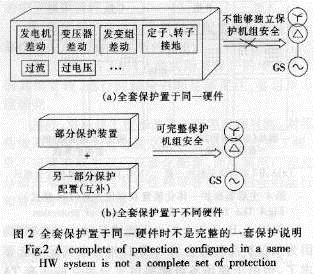
b. "Misunderstanding" 2: Place the main backup full protection in the same hardware system. Since all the protections done in a set of hardware share the hardware, if the hardware fails, all the protections may be lost. While enjoying digital protection resources, we must also be aware of the risks of digital protection of large resources. At home and abroad, the method of decomposing multi-layer hardware systems proposed by academician Yang Chi-xun has been implemented. This can better serve primary equipment such as transformers and generators.
To illustrate the existence of this risk, take an extreme case as an example. If a unit starts from the security and reliability of the protection configuration, 30 protections need to be configured. However, if the method shown in Figure 2(a) is adopted, all 30 protections are placed in one set of hardware, and it is obviously impossible to independently perform protection. The crew's responsibility for safety is due to the fact that re-reliable hardware will also fail. Once a hardware circuit fails, the crew will completely lose the protection function. Using the method of avoiding risks and decomposing risks, the same 30 kinds of protections are reasonably distributed in two different hardware systems. As shown in Figure 2(b), not only the same protection configuration is achieved, but also the requirements of the procedures can be fully met.
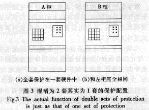
On the face of it, the number of protected species meets the requirements for double nesting, because the A and B cabinets contain the 30 protection configurations required by the crew. However, any one of the cabinets (A or B) cannot be a protection device that satisfies the requirements of the regulations alone. Therefore, Figure 3 is not a “double set†configuration in the true sense of the “Implementation Regulations.†In fact, it is just that. A set of configurations that meet the requirements of the procedure.
The main backup protection integrated device must realize the solution of "anti-practice regulations" in accordance with the solution of Figure 4. That is, A, B, C, D 4 engineering cabinets are used. A, B cabinets constitute a complete set, C, D cabinets constitute another set, together to form a double set of configuration. The mode of FIG. 4 is simply referred to as the 1x4 mode, which is applicable to the main backup protection integrated device.
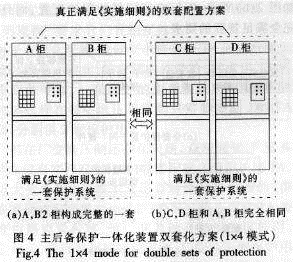
Obviously, the solution of Figure 4 takes up a lot of cabinet space and costs a lot. At the same time, TA must bear the load of 2 cabinets (such as A and B cabinets). TA is heavily reused, which reduces the security of the protection to some extent. The application is not desirable.
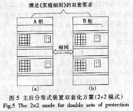
The 3.32+2 mode realizes the development of the double-encapsulation digital protection technology. It is easy to complete the full set of main backup protection with highly integrated hardware, but there is a huge risk. From the point of view of satisfying the requirements of regulations, the main backup protection distribution configuration should be adopted to avoid the risks caused by high integration.
For a long time, the design concept of “strengthening primary protection and simplifying backup protection†has been formed in the protection of the main equipment. The guiding ideology is to strengthen the main protection that plays a leading role in the unit, such as differential, stator grounding, overvoltage, and magnetic loss. , Simplified protection from backup. At the same time, it is pointed out that due to the complex fault of the unit, the actual fault process is far from being analyzed accurately and completely. Therefore, the complementary protection of different principles and schemes is encouraged to be applied at the same time to maximally protect the unit's safety.
At the same time, the rational separation and mutual independence of primary protection and backup protection are conducive to the protection of security.
For a 300MW unit, a single set needs to be equipped with generator longitudinal differential, transformer differential, generator-transformer differential, alternator split-phase differential, single-element differential, overvoltage, overexcitation, negative-sequence over-current, inverse-time negative. Order overcurrent protection. The following analyzes how to assign the configured protection from the perspective of reliability.
Because of the complementarity between the generator-transformer differentials and the generator differentials and transformer differential protections, there is complementarity between the generator cracking phase differential and the single element horizontal differential protection; there is complementarity between overvoltage and overexcitation; There is complementarity between negative-sequence over-current and negative-time negative-sequence over-current; etc. If such a complementarity between protection principles is taken into account in the protection configuration, it can be achieved optimally under the condition that the total configuration remains unchanged. The purpose of configuring the most reliable unit protection.
Figure 5 shows the specific implementation of this design (Figure 5 (a) is a complete set of protection to meet the "Anti-Countermeasures", and (b) Another set of protection to meet the "Anti-Countermeasures"). In the A-cabinet, two separate hardware systems are used. In a hardware system of the A-cabinet, generator differentials, transformer differentials, generator split-phase differentials, overvoltages, negative sequence overcurrents, and other protections are allocated. In another hardware system, there is distribution of differential protection, unit cell cross-over, over-excitation, inverse-time negative sequence over-current protection. When any hardware system in the A-cabinet fails, rapid protection still exists, and backup protection exists. At this time, it is still a complete set of main backup protection. In addition to the same configuration of the B cabinet, there is still an independent triple rapid protection that protects the unit. Therefore, the protection of the unit is still very safe and reliable. The mode of FIG. 5 is abbreviated as 2+2 mode, and the mode is applicable to a device configured for primary backup protection distribution.
3.5 ABB, Siemens Double Enclosure Scheme ABB constitutes a set of protections often using Reg216 + 216C or Reg 216 + 316 methods, thus constituting a solution to meet the "Reconciliation Rules", see Figure 6.
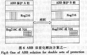
Siemens has always done a good job of avoiding high integration risks. It has already divided the protection into different hardware loops when assigning protection, which can better protect the unit's safety. Of course, if hardware is too decentralized, the cost will be greatly increased, and the improvement of security will no longer be obvious.
3.6 How to Determine Double Sets to Meet "Implementation Rules"
From the above analysis, it can be seen that whether the various double-entry solutions meet the “Implementation Rules†depends not only on the number of configurations, but also on specific analysis. Digital protection must avoid the risks associated with high integration. The simpler method is to divide the design process into two parts when designing the protection scheme.
a. In the protection of the configuration design, a set of protection design as a guiding ideology, this time the design should fully meet the requirements of the original regulations, to assess whether this set of long-term, independent, complete and safe completion of the protection function. If it can, then this is a complete set of protective devices.
b. The above set of repeated configuration, ie double set.
After the above two steps are taken into consideration, risks can be maximally avoided and some misunderstandings can be avoided.
4 Conclusions The "Anti-Countermeasure Implementation Regulations" proposed a dual-enclosure configuration requirement, and each set of protection must have a complete and independent main backup protection configuration. At the same time, each set of protections must be completely separated and independent from each other in electrical terms to improve the unit's performance. Protection ability and independent operation ability of a single protection device. In order to realize the above-mentioned objectives, it is necessary to strengthen coordination among various departments of design, manufacture, operation, and management to make the protection device truly safe and reliable, and to contribute to the safe and stable operation of the power system. The following conclusions are drawn from this analysis.
a. Two or more identical protections are placed in the same digital protection hardware and the effect is equivalent to one protection.
b. The main backup full protection is placed on a set of hardware systems. It is actually a set of incomplete protections. It cannot play a main backup role and does not meet the requirements of the regulations.
c. The double set of the main backup protection integrated device does not meet the requirements of the "Anti-countermeasure Implementation Rules."
The d.2+2 mode is suitable for relay protection of large-capacity main equipments. It satisfies the requirements of the double countermeasures of the "Reconsideration Regulations" and meets the requirements of relay protection regulations.
e. The “Anti-Countermeasure Implementation Regulations†actually increased the reliability requirements of the original N-1 implementation of digital protection to N-2 to ensure the safe and stable operation of the unit.
f. Digital protection shall comprehensively analyze the relationship between the protection configuration and the reliability of the protection device to ensure the safety of the unit.
It is recommended that the management and operation issues arising from the increase of sharing and protection of TAs and TVs after double-sets should arouse enough attention and organize special research.
In addition, new construction and renovation projects need to be treated differently. For those renovation projects that can not be completely independent of electrical double protection, it should not be forced to double-dual-double-dual-enclosed configuration, but should be brainstorming to fully complete the security and reliability of a single set of protection, otherwise it will be run. And management brings a lot of inconvenience.
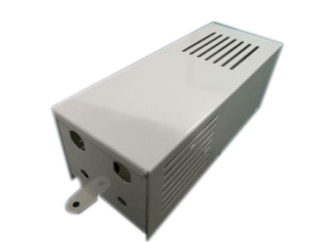
Metal stamping Audio Metal Chassis Panel
Timeplex knows how to take a design from function, shape and fit, to a quality stamping part that canStamping dies design be manufactured consistently and stablely, we own inhouse tools/dies design department consist of 4 dynamic and veteran engineers who are dedicated to tools, dies, design for at least 10 years in metal stamping and sheet metal parts fields and served at FOXCONN and SAMSUNG etc which are 500 fortune in the world. ,
More services we offer:
Besides of Metal Stamping Components,the Amplifiers metel chassises and Panels, we also complete solution for OEM/ODM Products & components, offer services of deep drawing services, EMI metal shielding parts, heat sink ,plastic molding products for custom, Plastic Injection Components, Metal Stamping Parts, home appliances accessories ,R/C drone and smart electronic toys etc.
We have been a professional OEM/ODM metal stamping (Aluminum,stainless steel,Copper ,SPCC,SGCC and so on) manufacturer for 30 years in China. Our Products application: Consumer electronic hardware accessories such as telecommunication aluminum cavity,LED Lighting aluminum housing,Setup box housing,power adapter case ,UPS power housing,STB box,AMPLIFIERS chassis and panel LED driver case ;Thermal solution heat sinks&radiator;Computer hardware accessories;Furniture hardware parts,home appliance etc.
Products informations:
Surface treament:Anodizing, powder coating,painting bonding, sand blasting, buffering and assembling,Zinc-plated, nicke plated, chrome-plated, silver-plated, gold-plated,Passivation etc.
All parts are customized according to customer's drawings or samples. If you have any parts to beproterotype, please feel free to send your drawings/samples to us
Audio Metal Chassis Panel,Amplifiers Metal Chassis,Metal Enclosure Box,Project Box Enclosure
Timeplex Industrial Limited , https://www.hktimeplex.com
