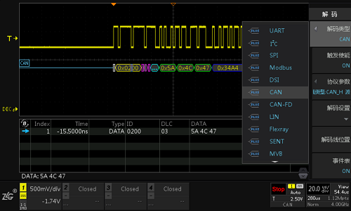
Protocol decoding is a very practical function of the oscilloscope. Many engineers do not get the ideal result because they are not familiar with the operation or the parameter settings are incorrect. This article introduces a few details about the decoding settings to help you get started with the oscilloscope's protocol decoding.
First, decoding
Decoding is a process of converting electrical pulse signals, optical signals, radio waves, etc. into information, data, etc., represented by a specific calculation method. Decoding is the process of restoring the received symbols or codes into information by the sender. Corresponding to the encoding process, different decoding methods are different protocols. After years of development, the oscilloscope and the oscilloscope can directly decode the waveform data. Presented in hexadecimal, decimal or character form, and compatible with a wide variety of protocols.

Second, the sampling rate
The first point to focus on is the sampling rate, and the oscilloscope decodes the acquired waveform data. If the real-time sampling rate of the waveform acquisition is insufficient, it may affect the decoding result. The ZDS4054Plus oscilloscope comes standard with a 512M memory depth, which guarantees a high sample rate for long-term capture waveforms. After all, only the correct waveform is captured to get the correct decoding.
Third, the protocol parameter settings
Protocol parameter setting is the most important part of decoding success. Different settings may result in different decoding results or may not be decoded. In actual application, half of the cases are caused by ignoring some settings and causing decoding errors.
The first is to select the correct protocol type and "trigger enable" to select "ON", the signal will be triggered according to the start bit, data bit or address bit of the protocol.
Followed by the parameter setting, you can enter the corresponding parameter settings by clicking "Protocol Parameters", set the corresponding parameters according to different needs, and pay attention to check whether the "trigger setting" below is consistent with the preset method.

Fourth, the threshold setting
The threshold setting is the most easily overlooked point in the usual decoding. When the oscilloscope decodes the waveform, it needs a reference baseline. The oscilloscope compares the waveform data with respect to the value of the baseline to judge the high and low levels. Generally, the oscilloscope default threshold is an automatic threshold. That is, the intermediate value between the maximum value and the minimum value is automatically confirmed. For example, the CAN-H level is 3.5V, and the CAN-L level is 1.5V. If there are only CAN-H and CAN-L in the screen, then the threshold It is 2.5V. At this time, the high and low levels can be well recognized. If the waveform in the screen starts from -3.5V and then the CAN signal is triggered, the threshold is OV. At this time, CAN-L will also be recognized as high. Level, resulting in decoding errors. So when there is a particularly large deviation between the high and low levels in the screen, you may need to manually set the threshold.

Frame integrity
Sometimes, the waveform captured in the screen may not be a complete frame, so the oscilloscope can't complete the decoding. You can try to enlarge the time base and capture multiple frames in one screen to ensure that there is at least one complete screen. frame.
Automatic Pressure Pump,Force Pressure Control,Pressure Control Switch,Automatic Pressure Control
Ningbo Metal Sharing Supply Chain Management Co., Ltd , https://www.sheetsharing.com
